Rick Gallaher, CISSP, is owner of Dragonfly Associates LLC http://dragonfly-associates.
Building a fault-tolerant, rapid recovery network is new to the data world. One reason is that data communications philosophy is that the data will get there or it will be retransmitted. This philosophy does not work well in voice networks. To make MPLS competitive with ATM and on par with voice networks, rapid recovery must be implemented.
There are several methods under study to provide network protection. Vendors recommend approaches that are supported by their overall design concepts and specifications; therefore, failure recovery is not necessarily interoperable among different vendors. Design teams must carefully select vendors with interoperable recovery methods.
The failure recovery method that has received much favorable press lately is RSVP-TE. The soft-state operations of RSVP-TE make it very suitable for failure recovery. One reason is that the polling (reservation/path) functions are already in place for signaling. If RSVP-TE is already used for a signaling protocol, it makes a logical selection to protect your MPLS tunnels.
MPLS Resource Sites:
Special Thanks
I would like to thank Ben Gallaher, Susan Gallaher, and Amy Quinn for their assistance, reviewing, and editing.
A special thank you to all those who assisted me with information and research on the MPLSRC-OP /mail list, especially: Robert Raszuk.
Rick Gallaher, CISSP, is owner of Dragonfly Associates LLC http://dragonfly-associates.
This series of tutorials has defined MPLS into two operations: data flow and signaling. The previous tutorials have addressed these subjects with special attention given to signaling protocols CR-LDP and RSVP-TE. To complete this series, this article will cover the failure recovery process.
Vocabulary
- Back-up Path: the path that traffic takes if there is a failure on the primary path.
- Fast ReRoute (FRR): a protection plan in which a failure can be detected without a need for error notification or failure signaling (Cisco).
- Link Protection: a backup method that replaces the entire link or path of a failure.
- Make Before Break: a procedure in which the back-up path is switched in before the failed path is switched out. For a small period of time, both the primary and back-up paths carry the traffic.
- Node Protection: a backup procedure in which a node is replaced in a failure.
- Pre-provisioned Path: a path in the switching database on which traffic engineering has been performed in order to accommodate traffic in case of a failure.
- Pre-qualified Path: a path that is tested prior to switchover that meets the quality of service (QoS) standards of the primary path.
- Primary Path: the path through which the traffic would normally progress.
- Protected Path: a path for which there is an alternative back-up path.
- Rapid ReRoute (RRR): a protection plan in which a failure can be detected without a need for error notification or failure signaling (Generic).
Introduction
Around the country you will find highways under repair. A good many of these highways have bypass roads or detours to allow traffic to keep moving around the construction or problem areas. Traffic rerouting is a real challenge for highway departments, but they have learned that establishing detour paths before construction begins is the only way they can keep traffic moving (Figure 1).
Figure 1: Traffic Detour
The commitment to keeping traffic moving has been a philosophy in voice and telephone communications since its inception. In a telephony network, not only are detour paths set-up before a circuit is disconnected (make before break), but the back-up or detour paths must have at least the same quality as the links that are to be taken down for repair. These paths are said to be pre-qualified (tested) and pre-provisioned (already in place).
Historically in IP networking, packets would find their own detours around problem areas; there were no pre-provisioned bypass roads. The packets were in no particular hurry to get to the destination. However, with the convergence of voice onto data networks, the packets need these bypass roads to be pre-provisioned so that they do not have to slow down for the construction or road failures.
The Need for Network Protection
MPLS has been primarily implemented in the core of the IP network. Often, MPLS competes head-to-head with ATM networks; therefore, it would be expected to behave like an ATM switch in case of network failure.
With a failure in a routed network, recovery could take from a few tenths of a second to several minutes. MPLS, however, must recover from a failure within milliseconds – the most common standard is 60 ms. To further complicate the recovery process, an MPLS recovery must ensure that traffic can continue to flow with the same quality as it did before the failure. So, the challenge for MPLS networks is to detect a problem and switch over to a path of equal quality within 60ms.
Failure Detection
There are two primary methods used to detect network failures: heartbeat detection (or polling) and error messaging. The heartbeat method (used in fast switching) detects and recovers from errors more rapidly, but uses more network resources. The error-message method requires far less network resources, but is a slower method. Figure 2 shows the tradeoffs between the heartbeat and error-message methods.
Figure 2: Heartbeat vs. Error Message
The heartbeat method (Figure 3) uses a simple solution to detect failures. Each device advertises that it is alive to a network manager at a prescribed interval of time. If the heartbeat is missed, the path, link, or node is declared as failed, and a switchover is performed. The heartbeat method requires considerable overhead functions - the more frequent the heartbeat, the higher the overhead. For instance, in order to achieve a 50ms switchover, the heartbeats would need to occur about every 10ms.
Figure 3: Heartbeat Method
The other failure detection system is called the error-message detection method (Figure 4). When a device on the network detects an error, it sends a message to its neighbors to redirect traffic to a path or router that is working. Most routing protocols use adaptations of this method. The advantage of the error message is that network overhead is low. The disadvantage is that it takes time to send the error-and-redirect message to the network components. Another disadvantage is that the error messages may never arrive at the downstream routers.
Figure 4: Error Message
If switchover time is not critical (as it has historically been in data networks), the error-message method works fine; however, in a time-critical switchover, the heartbeat method is often the better choice.
Reviewing Routing
Remember that, in a routed network (Figure 5), data is connectionless, with no real quality of service (QoS). Packets are routed from network to network via routers and routing tables. If a link or router fails, an alternative path is eventually found and traffic is delivered. If packets are dropped in the process, a layer-4 protocol such as TCP will retransmit the missing data.
Figure 5: Standard Routing
This works well when transmitting non-real time data, but when it comes to sending real-time packets, such as voice and video, delays and dropped packets are not tolerable. To address routing-convergence problems, the OSPF and IGP working groups have developed IGP rapid convergence, which reduces the convergence time of a routed network down to approximately one second.
The benefits of using IGP rapid convergence include both increased overhead functions and traffic on the network; however, it only addresses half of the problem posed by MPLS. The challenge of maintaining QoS parameter tunnels is not addressed by this solution.
Network Protection
In a network, there are several possible areas for failure. Two major failures are link failure and node failure (Figure 6). Minor failures could include switch hardware, switch software, switch database, and/or link degradation.
Figure 6: Network Failures
The telecommunication industry has historically addressed link failures with two types of fault-tolerant network designs: one-to-one redundancy and one-to-many redundancy. Another commonly used network protection tactic utilizes fault-tolerant hardware.
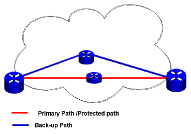
To protect an MPLS network, you could pre-provision a spare path with exact QoS and traffic-processing characteristics. This path would be spatially diverse and would be continually exercised and tested for operations. However, it would not be placed online unless there were a failure on the primary protected path.
This method, known as one-to-one redundancy protection (Figure 7), yields the most protection and reliability, but its cost of implementation can be extreme.
Figure 7: One-to-One Redundancy
A second protection scheme is one-to-many redundancy protection (Figure 8).
In this method, when one path fails, the back-up path takes over. The network shown in the Figure 8 can handle a single path failure, but not two path failures.
Figure 8: One-to-Many Redundancy
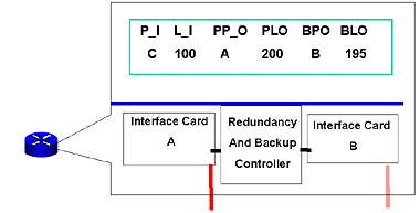
A third protection method is having fault tolerant switches (Figure 9). In this design, every switch features inbuilt redundant functions – from power supplies to network cards. The drawing shows redundant network cards with a back-up controller. Take note that the one item in common, and not redundant, is the cross-connect tables. If the switching data becomes corrupt, the fault tolerant hardware cannot address this problem.
Figure 9: Fault Tolerant Equipment
Now that you know the three network protection designs (one-to-one, one-to-many, and fault-tolerant hardware) and two methods for detecting a network failure (heartbeat and error message), we need to talk about which layers and protocols are responsible for fault detection and recovery.
Remembering that the further the data progresses up the OSI stack, the longer the recovery will take, it makes sense to attempt to detect failures at the physical level first.
MPLS could rely on the layer-1 or layer-2 protocols to perform error detection and correction. MPLS could run on a protected SONET ring, or it could use ATM and Frame Relay fault-management programs for link and path protection. In addition to the protection MPLS networks could experience via SONET, ATM or Frame Relay, IP has its recovery mechanism in routing protocols, such as OSPF or IGP.
With all these levels of protection already in place, why does MPLS need additional protection? Because there is no protocol that is responsible for ensuring the quality of the link, tunnel, or call placed on an MPLS link. The MPLS failure-recovery protocol must not only perform rapid switching, but it must also ensure that the selected path is pre-qualified to take the traffic loads while maintaining QoS conditions. If traffic loads become a problem, MPLS must be able to offload lower-priority traffic to other links.
Knowing that MPLS must be responsible for sending traffic from a failed link to a link of equal quality, let’s look at the two error-detection methods as they apply to MPLS.
MPLS Error Detection
The LDP and CR-LDP protocols contain an error message type-length value (TLV) in their protocols to report link and node errors. However, there are two main disadvantages to this method: (1) it takes time to send the error message, and (2) since LDP is a connection-oriented message, the notification message may never arrive if the link is down.
An alternative approach to error detection is to use the heartbeat method that is found at the heart of the RSVP-TE protocol. RSVP has features that make it a good alternative for an error- message model. RSVP is a soft-state protocol that requires refreshing – i.e., if the link is not refreshed, then the link is torn down. No error messages are required, and rapid recovery (rapid reroute) is possible if there is a pre-provisioned path. If RSVP-TE is already used as a signaling protocol, the additional overhead needed for rapid recovery is insignificant.
Rapid reroute is a process in which a link failure can be detected without the need for signaling. Because RSVP-TE offers soft-state signaling, it can handle a rapid reroute.
Many vendors are using the RSVP-TE for rapid recovery of tunnels and calls, but in doing so, other MPLS options are restricted. For example, labels are allocated per switch, not per interface. Another restriction is that RSVP-TE must be used for a signaling protocol.
RSVP-TE Protection
In RSVP-TE protection, there are two methods used to protect the network: link protection and node protection.
In link protection, a single link is protected with a pre-provisioned backup link. If there is a failure in the link, the switches will open the pre-provisioned path (Figure 10).
Figure 10: RSVP-TE with Link Protection
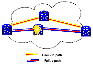
In a node failure, an entire node or switch could fail, and thus, all links attached to the node will fail. With node protection, a pre-provisioned tunnel is provided around the failed node (Figure 11).
Figure 11: RSVP-TE with Node Protection
Thrashing Links
A discussion about fault-tolerant networks would not be complete without mentioning thrashing links. Thrashing is a phenomenon that occurs when paths are quickly switched back and forth. For example: In a network with two paths (primary and back-up), the primary path fails and the back-up path is placed in service. The primary path self-heals and is switched back into service, only to fail again.
Thrashing is primarily caused by intermittent failures of primary paths and pre-programmed switchback timers. In order to overcome thrashing, the protocols and the switches must use hold-down times. For example, some programs allow one minute for the first hold-down time and set a trigger so that on the second switchback, operator intervention is required to perform a switchover and to prevent thrashing.
Summary
Building a fault-tolerant, rapid recovery network is new to the data world. One reason is that data communications philosophy is that the data will get there or it will be retransmitted. This philosophy does not work well in voice networks. To make MPLS competitive with ATM and on par with voice networks, rapid recovery must be implemented.
There are several methods under study to provide network protection. Vendors recommend approaches that are supported by their overall design concepts and specifications; therefore, failure recovery is not necessarily interoperable among different vendors. Design teams must carefully select vendors with interoperable recovery methods.
The failure recovery method that has received much favorable press lately is RSVP-TE. The soft-state operations of RSVP-TE make it very suitable for failure recovery. One reason is that the polling (reservation/path) functions are already in place for signaling. If RSVP-TE is already used for a signaling protocol, it makes a logical selection to protect your MPLS tunnels.
MPLS Resource Sites:
| A Framework for MPLS Based Recoveryhttp://www.ietf.org/internet-drafts/draft-ietf-mpls-recovery-frmwrk-03.txt |
| Surviving Failures in MPLS Networkshttp://www.dataconnection.com/download/mplsprotwp.pdf |
| MPLS Links Pagehttp://www.rickgallaher.com/ (click on the MPLS Links tab) |
| Network Traininghttp://www.globalknowledge.com |
Special Thanks
I would like to thank Ben Gallaher, Susan Gallaher, and Amy Quinn for their assistance, reviewing, and editing.
A special thank you to all those who assisted me with information and research on the MPLSRC-OP /mail list, especially: Robert Raszuk.
Rick Gallaher, CISSP, is owner of Dragonfly Associates LLC http://dragonfly-associates.


