Showing posts with label Tutorial. Show all posts

Sunday, December 8, 2013

Blueprint Tutorial: SDN and NFV for Optimizing Carrier Networks, Part II

By Raghu Kondapalli, Director of Strategic Planning at LSI

This is the second article in a two-part series. The first article, which discussed the drivers, benefits and trends of unified datacenter-carrier networks, and introduced SDN and NFV technology, is available here.

This article provides some examples of how SDN and NFV can be applied to various segments of a carrier network, and how the functions of a traditional carrier network can be offloaded to a virtualized datacenter to improve end-to-end performance.

Application of SDN and NFV to a Unified Datacenter-Carrier Network

With roots in voice, carrier networks are connection-oriented, while datacenter networks, with roots in data, utilize connectionless protocols. Carriers wanting to fully integrate its datacenter(s) will, therefore, need a common set of protocols. Possible choices include VxLAN (Virtual Extensible LAN) and NvGRE (Network Virtualization using Generic Routing Encapsulation), which are both extensible and scalable with the ability to support thousands of virtual machines (VMs), as well as tunneling protocols, such as IPSec, which can be used to establish end-to-end virtual private networks (VPNs).

In addition to these well-known protocol-level techniques, network-level abstraction based on SDN similarly enables the integration of datacenter and carrier networks. Here are two examples.

Offloading of network control functions to a centralized datacenter using SDN

Control plane components, such as discovery and dissemination of network state, can be decoupled and executed in a centralized datacenter using commodity servers. Centralizing the control plane has the advantage of providing an end-to-end network state view, and enables the network operator to allocate hardware resource pools based on different application needs. Centralizing the control plane also enables the network operator to use standard APIs to monitor and manage the network, and to provision the network according to changing conditions, such as the number of active subscribers.

Offloading of network application software to a virtualized datacenter using SDN

SDN’s centralized control platform for managing hardware resources also supports the virtualization and execution of core applications in one or more datacenters. For a “software-on-demand” capability, for example, a network operator could designate core application software to run on any hardware platform in any datacenter that provides the required processing capacity. Or to provide LTE services in a certain city, the operator might program serving gateway (SGW) or mobility management entity (MME) software to run on a local platform. A major benefit of having network services being fully abstracted is that the operator need not manage the underlying hardware.

Application of SDN and NFV to Carrier Network Segments

Carrier networks are composed of access networks, transport or backhaul networks, and core networks as shown in Figure 6. Note the use of both connection-oriented (Time Division Multiplexing and Asynchronous Transfer Mode) and connectionless (IP) networks end-to-end across the infrastructure.

Applying virtualization schemes based on SDN and NFV enables the entire carrier network to run on a common, commodity and multi-purpose hardware resource pool. This reduces network cost and complexity significantly, which also simplifies network management. By leveraging centralized control and virtualized hardware platforms, core applications share a common hardware pool that improves both scalability and resource utilization. The use of virtualized resource pools can also enable new services and upgrades to be implemented in many cases without costly hardware upgrades.

Figure 7 shows a conceptual view of the SDN-based carrier network. Note how the hardware platform is decoupled from the software platform, and how this enables different cellular technologies to run as virtualized network elements concurrently and independently of any specific hardware platform.

Application of SDN and NFV to Core Networks

Mobile core networks consist of network elements that reside between connection-oriented radio access networks (RANs) and connectionless backbone networks, including the Internet, that employ packet switching. Core networks now also need to support a growing variety of cellular technologies, including 3G, LTE and 4G—all concurrently. The underlying core network functions, such as packet forwarding, as well as control tasks, such as mobility management, session handling and security, are implemented today using dedicated network elements.

Consider, for example, an SGW that forwards packets and an MME that is responsible for activation or authentication in an LTE network. Because these functions are typically executed on common and proprietary hardware platforms, they are visible to one another, resulting in management, resource sharing and security problems. Abstraction with SDN enables the use of commodity hardware, while also mitigating the management, resource sharing and security issues.

Another example is shown in Figure 8. In this example, dedicated application software, which implements network functions for each dedicated core network element like MME or Gateway and Serving GPRS Support Nodes (GGSN and SGSN), can be virtualized and centralized with SDN to run in a private cloud, on virtualized commercial server platforms, or on multi-vendor, non-proprietary hardware.

Application of SDN and NFV to Carrier Access Networks

Subscribers interface with the carrier network via basestation nodes in the RAN, as shown in Figure 6. Owing to the explosion in mobile device adoption and mobile data usage worldwide, the RAN must now be optimized to address these challenges:

  • rapid increase in the number of more closely-spaced base stations needed to cover a given area with LTE eNodeB deployments
  • relatively low basestation utilization with relatively high power consumption
  • similarly low utilization of RF bandwidth resulting from RF interference and limited network capacity in a multi-standard environment
Virtualization of resources in a basestation based on SDN and NFV holds tremendous promise for confronting these and other challenges. As shown in Figure 9, the virtualized real-time operating system and the multiple, multi-standard basestation instances run on top of resource pools, which have been allocated from the physical processing resources. The virtualized operating system dynamically allocates the processing resources based on each virtualized basestation’s changing requirements. Virtualization also enables different basestation instances using different standards and different application software to be provisioned dynamically through resource reconfigurations performed exclusively in software.

Under an SDN architecture, basestation pools with high-bandwidth, low-latency interconnects can be centralized to form virtualized “basestation clouds.” A centralized control plane, which has a global view of all physical processing resources throughout the cloud, enables network operators to program basestation processing tasks for different standards. For example, operators can deploy 3G or 4G RANs by programming different virtual basestations, and then adjust the capacity of each, all through software reconfigurations.

Figure 10 shows an implementation of such a “Cloud-based RAN” (C-RAN) architecture that has been proposed by China Mobile (CMCC). The wireless remote radios connect to a cloud-based, virtualized basestation cluster, which can be implemented using SDN running on heterogeneous hardware processors.

Application of SDN and NFV to Carrier Transport Networks

The transport network in a wireless infrastructure serves as the backhaul network connecting the basestations in the access network to the core network. Transport networks can utilize many different technologies, including SONET, TDM, carrier Ethernet and IP, each of which exhibits different operating characteristics. For example, TDM has a simple operational model characterized by static routes and traffic flows across the network’s centralized control. By contrast, the IP network operational model routes traffic packet-by-packet across the network under distributed network control.

SDN is able to combine these different networking technologies in a way that leverages their respective strengths; in the example above, the simplicity of static network routing is combined with the flexibility and economic advantages of IP. This is possible because SDN decouples the network control and traffic-forwarding functions, thereby eliminating any interdependencies. For this reason, a distributed transport network element is able to support both static routes and dynamic traffic flows.

Summary

The telecommunications industry today, fueled by exploding growth in mobile subscribers and data usage, is undergoing an unprecedented transformation. As a result, service providers are under enormous pressure to deploy new value-added services while lowering costs to remain competitive. To achieve these objectives, carriers are integrating datacenters into their networks to create a more versatile and affordable unified datacenter-carrier network model.

Service providers also need to increase average revenue per user (ARPU) while reducing capital and operational expenditures through hardware consolidation, network resource optimization and ease-of-service deployment. Virtualization is a proven technology that has been adopted universally in datacenters to enhance resource utilization and scalability. By extending virtualization principles to the carrier infrastructure, service providers can optimize the unified datacenter-carrier network end-to-end and top-to-bottom.

Software-defined Networking and Network Function Virtualization enable this versatility in all three segments of a carrier network. SDN enables network functions and applications to leverage virtualized datacenter resources, while a combination of SDN and NFV enables carriers to deploy and scale innovative services more cost-effectively than ever before.

 Raghu Kondapalli is director of technology focused on Strategic Planning and Solution Architecture for the Networking Solutions Group of LSI Corporation.

Kondapalli brings a rich experience and deep knowledge of the cloud-based, service provider and enterprise networking business, specifically in packet processing, switching and SoC architectures.

Most recently he was a founder and CTO of cloud-based video services company Cloud Grapes Inc., where he was the chief architect for the cloud-based video-as-a-service solution.  Prior to Cloud Grapes, Kondapalli led technology and architecture teams at AppliedMicro, Marvell, Nokia and Nortel. Kondapalli has about 25 patent applications in process and has been a thought leader behind many technologies at the companies where he has worked.

Kondapalli received a bachelor’s degree in Electronics and Telecommunications from Osmania University in India and a master’s degree in Electrical Engineering from San Jose State University.

Thursday, January 24, 2002

Tutorial: MPLS Traffic Engineering

Rick Gallaher, CISSP, is owner of Dragonfly Associates LLC http://dragonfly-associates.com and author of  Rick Gallaher's MPLS Training Guide

January 24, 2002

In previous articles, we discussed data flow, signaling, and rapid recovery. This article addresses the subject of traffic engineering.

Vocabulary:
  • Silence Suppression:  Not using bandwidth when there is no data to send.
  • CR-LDP: Constraint Route Label Distribution Protocol.
  • Over-provisioning:  Having more bandwidth than allocated traffic.
  • Over-subscribing: Having more allocated traffic than available bandwidth. (Telco)
  • RSVP-TE: Resource Reservation Setup Protocol with Traffic Engineering
  • Under-subscribing: Having more bandwidth than allocated traffic. (Telco)
  • Under-provisioning: Having more allocated traffic than available bandwidth.
Introduction:

There is a road in Seattle, Washington that I drove years ago called Interstate 5.  From the suburb of Lynnwood, I could get on the highway and drive into the city, getting off at any exit.  If I wanted to go from Lynnwood into the heart of Seattle, I could get onto the express lanes.  This express lane is like an MPLS tunnel.  If my driving characteristics matched the requirements of the express lane, then I could use it.


Figure 5.1: Express Lane

Taking this illustration further, let’s say that I enter the freeway and want to drive into the heart of Seattle. I might ask myself, “Which is faster: the express lane or the regular highway? Is there an accident on the express lane?  Is the standard freeway faster?”

It would be nice to have traffic report, but traffic reports are not given in real time – by the time that I would find out about a slowdown, I would be stuck in it.  I could make the mistake of entering the express lane just as an accident happens 5 miles ahead and be trapped for hours.

It would be great if I had a police escort.  The police would drive in front of me; if there were an accident or a slowdown, then they would take me on a detour of similar quality to ensure that I arrive at my destination on time.

On the Internet, we have thousands of data roads just like Interstate 5. With MPLS, we have a road dedicated to traffic with certain characteristics – much like the express lane. To ensure that the express lane is available and free of congestion, we can use protocols like CR-LDP and RSVP-TE.  These protocols are discussed in greater detail in the article Advanced MPLS Signaling.  Currently, the most popular of these two protocols appears to be RSVP-TE, because it acts like a police escort to ensure that, if there is congestion, it can be re-routed around the problem area.

When looking at traffic patterns around the country, often freeways experience congestion and delays, while other roads are open and allow traffic to flow freely. The traffic is just in the wrong area. Wouldn’t it be nice if the highway engineers and the city planners could find ways to route heavy traffic to roads that could handle the traffic load and to adjust the road capacity as needed to accommodate traffic volume?


Traffic Engineering

In data and voice networks, traffic engineering is used to direct traffic to the available resources.  If achieving a smooth-flowing network by moving traffic around were simple, then our networks would never experience slowdowns or rush hours.

On the Internet (as with highways), there are four steps that must be undertaken to achieve traffic engineering: measuring, characterizing, modeling, and moving traffic to its desired location.


Figure 5.2: Four Aspects of Traffic Engineering

Measuring traffic is a process of collecting network metrics, such as the number of packets, the size of packets, packets traveling during the peak busy hour, traffic trends, applications most used, and performance data (i.e., downloading and processing speeds).

Characterizing traffic is a process that takes raw data and breaks it into different categories so that it can be statistically modeled. Here, the data that is gathered in the measurement stage is sorted and categorized.

Modeling traffic is a process of using all the traffic characteristics and the statistically analyzed traffic to derive repeatable formulas and algorithms from the data. When traffic has been mathematically modeled, different scenarios can be run against the traffic patterns.  For instance, “What happens if voice/streaming traffic grows by two percent a month for four months?”  Once traffic is correctly modeled, then simulation software can be used to look at traffic under differing conditions.

Putting traffic where you want it: To measure, characterize, and model traffic for the entire Internet is an immense task that would require resources far in excess of those at our disposal. Before MPLS was implemented, we had to understand the characteristics and the traffic models of the entire Internet in order to perform traffic engineering.

When addressing MPLS traffic engineering, articles and white papers tend to focus on only one aspect of traffic engineering.  For example, you may read an article about traffic engineering that addresses only signaling protocols or one that just talks about modeling; however, in order to perform true traffic engineering, all four aspects must be thoroughly considered.

With the advent of MPLS, we no longer have to worry about the traffic on all of the highways in the world. We don’t even have to worry about the traffic on Interstate 5. We just need to be concerned about the traffic in our express lane – our MPLS tunnel. If we create several tunnels, then we need to engineer the traffic for each tunnel.

Provisioning and Subscribing

Before looking at the simplified math processes for engineering traffic in an MPLS tunnel, a brief discussion of bandwidth provisioning and subscribing is needed. 

First, let’s look at the definitions. Over-provisioningis the engineering process in which there are greater bandwidth resources than there is network demand.  Under-provisioning is the engineering process in which there is greater demand than there are available resources.  “Provisioning” is a term typically used in datacom language.

In telecom language, the term “subscribe” is used instead of “provision.” Over-subscribing is the process of having more demand than bandwidth, while under-subscribing is a process of having more bandwidth than demand.  It is important to note that provisioning terms and subscription terms refer to opposite circumstances.


A pipe/path/circuit that has a defined bandwidth (e.g., a “Cat-5” cable) can in theory process 100 Mb/s, while an OC-12 can process 622 Mb/s. These are bits crossing the pipe and comprise all overhead and payload bits.

In order to determine the data throughput at any given stage, you can measure the data traveling through a pipe with relative accuracy by using networking-measurement tools.  Using an alternate measurement method, you can calculate necessary bandwidth by calculating the total payload bits per second and adding the overhead bits per second; this second method is more difficult to calculate and less accurate than actually measuring the pipe.

If the OC-12, which is designed to handle 622 Mb/s, is fully provisioned and the traffic placed on the circuit is less than 622 Mb/s, it is said to be over-provisioned. By over-provisioning a circuit, true Quality of Service (QoS) has a better chance of becoming a reality; however, the cost per performance is significantly higher.

If the traffic that is placed on the OC-12 is greater than 622 Mb/s, then it is said to be under-provisioned.  For example, commercial airlines under-provision as a matter of course, because they calculate that 10-15% of their customers will not show up for a flight. By under-provisioning, the airlines are assured of full flights; but they run into problems when all the booked passengers show up for a flight.  The same is true for network engineering – if a path is under-provisioned, then there is a probability that there will be a problem of too much traffic.  The advantage of under-provisioning is a significant cost savings; the disadvantages are loss of QoS and reliability.


Figure 5-3:  Over-Provisioning v. Under-Provisioning

In figure 5-3, you can see that you can over- or under-provision a circuit in percentages related to the designed bandwidth.


Figure 5-4: Comparison of Over Provisioning and Under Provisioning


Calculating How Much Bandwidth You Need

For the sake of discussion in these examples, let’s assume that you know the characteristics of your network. This is a process of gathering data that is unique to your situation and has been measured by your team.

Example One:  Two tunnels with load balanced OC-12 designed for peak busy hour.
Let’s say that we want to engineer traffic for an OC-12 pipe, which is 622 Mbps.
You want to have rapid recovery, so you use two pipes and load balance each pipe for 45% of capacity.  In this case, if one OC-12 pipe fails, then your rapid recovery protocol can move traffic from your under-provisioned pipe to the other, and the total utilization is still under-provisioned.

Figure 5-5: Sample Network Diagram Example One


Figure 5-6: Sample Network Failure


Figure 5-7 Traffic Trends
We can work these numbers just like we would in a checkbook. After we do the math, if we still have money (bits) remaining, then we are okay.  If our checkbook comes out in the red, then we must go back and budget our spending.

The following table helps to simplify the bandwidth budgeting process, as well as demonstrate some of the calculations involved in traffic engineering.Our traffic trends for peak busy hour show that we have:

Traffic DemandsTotals and subtotals
Number of voice calls100
      b/s/call200,000
      Total voice
      streams in b/s
20,000,00020,000,000
Number of video calls3
      b/s/call500,000
      Total video
      streams in b/s
1,500,0001,500,000
Committed information rate250,000,000250,000,000
Other traffic00
Total traffic demand271,500,000271,500,000BW required
Bandwidth  Available
  Circuit bandwidth
  for  OC-12
622,000,000
  Percentage used45%Over-
provisioned
  Total BW for
  over-provisioned
279,900,000279,900,000BW on-hand
271,500,000BW required
Remaining Bandwidth8,400,000BW remaining
       Key
       BW = Bandwidth
       b/s = bits per second
       b/s/call = bits per second for each call


Figure 5-8:  Traffic Engineering Calculations for Example One

Now that we understand the basic concept, let’s play with the figures a bit to achieve the outcomes that we need.

Example 2:  Example with Silence Suppression

First, let’s say that we are going to use “silence suppression” on the voice calls. Silence suppression means that we will not use bandwidth if we are not transmitting.  The effects of silence suppression can be seen in Figure 5-9 below, which is a simple 10 count over 10 seconds.

The lows in the graph indicate the periods in which no data is being sent.  Silence suppression can be used if the calls have the characteristics of phone calls (Figure 5-9). However, if the calls are streaming voice like a radio show, or piped-in music (Figure 5-10), notice that the baseline is higher, and that more overall bandwidth is used.


Figure 5-9: Voice with Silence Suppression


Figure 5-10:  Music Jazz (The Andrews Sisters singing “Boogie-Woogie Bugle Boy”)

We can reduce the number of bits required for voice calls down to100K by using silence suppression. Notice in the following table that we have more remaining bandwidth with which to work.

Traffic DemandsTotals and subtotals
Number of voice calls100
      b/s/call100,000
      Total voice
      streams in b/s
10,000,00010,000,000
Number of video calls3
      b/s/call500,000
      Total video
      streams in b/s
1,500,0001,500,000
Committed information rate250,000,000250,000,000
Other traffic00
Total traffic demand261,500,000261,500,000BW required
Bandwidth  Available
  Circuit bandwidth
  for 
622,000,000
  Percentage used45%Over-
provisioned
  Total BW for
  over-provisioned
279,900,000279,900,000BW on-hand
261,500,000BW required
Remaining Bandwidth18,400,000BW remaining
       Key
       BW = Bandwidth
       b/s = bits per second
       b/s/call = bits per second for each call


Figure 5-11: Traffic Engineering Calculations for Example Two


Example 3: Over Provisioned by 110%

Many carriers will choose over-provisioning because they cannot afford the cost of designing a highway system for rush hour traffic. Instead, they design a network for “normal traffic.”  Over-provisioning a network is similar to the airlines overbooking flights. There is a statistical point at which possible loss of customers is less than the cost of running planes at half capacity.

Let’s use the same example as above, with no switchable path and an OC-12 pipe that is able to tolerate some congestion during rush hour. We choose not to design the tunnel for peak busy-hour traffic; instead we design it for 10% over-provisioning, or 110% of the available bandwidth.

On paper this looks great, as we can still handle several hundred more calls, and it is an accountant’s dream. However, trouble lies in wait. What happens if all of the traffic arrives at the same time?  In addition, how can we handle a switchover to another link? If this link is provisioned at 110%, and the spare link is provisioned at 110%, one link will have a 220% workload during a single link failure, and will more than likely fail itself.


Traffic DemandsTotals and subtotals
Number of voice calls100
      b/s/call100,000
      Total voice
      streams in b/s
10,000,00010,000,000
Number of video calls3
      b/s/call500,000
      Total video
      streams in b/s
1,500,0001,500,000
Committed information rate250,000,000250,000,000
Other traffic00
Total traffic demand261,500,000261,500,000BW required
Bandwidth  Available
  Circuit bandwidth
  for  OC-12
622,000,000
  Percentage used110%Over-
provisioned
  Total BW for
  over-provisioned
684,200,000684,200,000BW on-hand
261,500,000BW required
Remaining Bandwidth422,700,000BW remaining
       Key
       BW = Bandwidth
       b/s = bits per second
       b/s/call = bits per second for each call

Figure 5-12:  Traffic Engineering Calculations for Example Three


Summary

Traffic engineering for MPLS consists of four elements: measurement, characterization, modeling, and putting traffic where you want it to be.  MPLS can use either traffic engineering protocols (CR-LDP or RSVP-TE) discussed in advanced signaling to put traffic where it is desired.  Of the two protocols, RSVP-TE appears to be more dominant, but it costs more in bandwidth – it is like paying for a police escort when you travel.
The rest of traffic engineering is far from simple. You must measure, characterize, and model the traffic that you want. Once you have the information that you need, you can then perform mathematical calculations to determine how much traffic can be placed on your tunnel.
The mathematical process is like balancing a checkbook; you should never allow the balance to go into the red or negative area.

The tradeoff decisions are difficult to make.  Can you over-provision (over-book) your tunnel and just hope that rush hour traffic never comes your way?  In the event of a failure, where is the traffic going to go?

Suggested URLs:


Traffic Modeling
http://www.comsoc.org/ci/public/preview/roberts.html 
Draft Math RFC
http://www.ietf.org/internet-drafts/draft-kompella-tewg-bw-acct-00.txt
Bell Labs
http://cm.bell-labs.com/cm/ms/departments/sia/InternetTraffic/
Traffic Engineering Work Group
http://www.ietf.org/html.charters/tewg-charter.html  
Inside the Internet Statistics
http://www.nlanr.net/NA/tutorial.html 
Excellent Measurement Site
http://www.caida.org/
Modeling and Simulation Software
HTTP://NetCracker.Com

Special Thanks

I would like to thank Ben Gallaher, Susan Gallaher, and Amy Quinn for their assistance in reviewing, and editing this article.

A special thank you to all those who assisted me with information and research on the MPLSRC-OP mail list, especially: Senthil Ayyasamy, Irwin Lazar, and Ashwin C. Prabhu.

Rick Gallaher, CISSP, is owner of Dragonfly Associates LLC http://dragonfly-associates.com

Rick is also the author of Rick Gallaher's MPLS Training Guide - Building Multi Protocol Label Switching Networks

Monday, December 17, 2001

Tutorial: MPLS Network Reliance and Recovery

Rick Gallaher, CISSP, is owner of Dragonfly Associates LLC http://dragonfly-associates.com and author of  Rick Gallaher's MPLS Training Guide

December 17, 2001

This series of tutorials has defined MPLS into two operations: data flow and signaling. The previous tutorials have addressed these subjects with special attention given to signaling protocols CR-LDP and RSVP-TE. To complete this series, this article will cover the failure recovery process.

Vocabulary
  • Back-up Path: the path that traffic takes if there is a failure on the primary path.
  • Fast ReRoute (FRR): a protection plan in which a failure can be detected without a need for error notification or failure signaling (Cisco).
  • Link Protection: a backup method that replaces the entire link or path of a failure.
  • Make Before Break: a procedure in which the back-up path is switched in before the failed path is switched out. For a small period of time, both the primary and back-up paths carry the traffic.
  • Node Protection: a backup procedure in which a node is replaced in a failure.
  • Pre-provisioned Path: a path in the switching database on which traffic engineering has been performed in order to accommodate traffic in case of a failure.
  • Pre-qualified Path: a path that is tested prior to switchover that meets the quality of service (QoS) standards of the primary path.
  • Primary Path: the path through which the traffic would normally progress.
  • Protected Path: a path for which there is an alternative back-up path.
  • Rapid ReRoute (RRR): a protection plan in which a failure can be detected without a need for error notification or failure signaling (Generic).
Introduction

Around the country you will find highways under repair.  A good many of these highways have bypass roads or detours to allow traffic to keep moving around the construction or problem areas.  Traffic rerouting is a real challenge for highway departments, but they have learned that establishing detour paths before construction begins is the only way they can keep traffic moving (Figure 1).


Figure 1: Traffic Detour

The commitment to keeping traffic moving has been a philosophy in voice and telephone communications since its inception. In a telephony network, not only are detour paths set-up before a circuit is disconnected (make before break), but the back-up or detour paths must have at least the same quality as the links that are to be taken down for repair. These paths are said to be pre-qualified (tested) and pre-provisioned (already in place).
Historically in IP networking, packets would find their own detours around problem areas; there were no pre-provisioned bypass roads. The packets were in no particular hurry to get to the destination. However, with the convergence of voice onto data networks, the packets need these bypass roads to be pre-provisioned so that they do not have to slow down for the construction or road failures.


The Need for Network Protection

MPLS has been primarily implemented in the core of the IP network. Often, MPLS competes head-to-head with ATM networks; therefore, it would be expected to behave like an ATM switch in case of network failure.
With a failure in a routed network, recovery could take from a few tenths of a second to several minutes. MPLS, however, must recover from a failure within milliseconds – the most common standard is 60 ms. To further complicate the recovery process, an MPLS recovery must ensure that traffic can continue to flow with the same quality as it did before the failure. So, the challenge for MPLS networks is to detect a problem and switch over to a path of equal quality within 60ms.

Failure Detection

There are two primary methods used to detect network failures: heartbeat detection (or polling) and error messaging. The heartbeat method (used in fast switching) detects and recovers from errors more rapidly, but uses more network resources.  The error-message method requires far less network resources, but is a slower method.  Figure 2 shows the tradeoffs between the heartbeat and error-message methods.


Figure 2: Heartbeat vs. Error Message

The heartbeat method (Figure 3) uses a simple solution to detect failures. Each device advertises that it is alive to a network manager at a prescribed interval of time. If the heartbeat is missed, the path, link, or node is declared as failed, and a switchover is performed.  The heartbeat method requires considerable overhead functions - the more frequent the heartbeat, the higher the overhead. For instance, in order to achieve a 50ms switchover, the heartbeats would need to occur about every 10ms.


Figure 3: Heartbeat Method

The other failure detection system is called the error-message detection method (Figure 4).  When a device on the network detects an error, it sends a message to its neighbors to redirect traffic to a path or router that is working.  Most routing protocols use adaptations of this method. The advantage of the error message is that network overhead is low. The disadvantage is that it takes time to send the error-and-redirect message to the network components. Another disadvantage is that the error messages may never arrive at the downstream routers.


Figure 4: Error Message

If switchover time is not critical (as it has historically been in data networks), the error-message method works fine; however, in a time-critical switchover, the heartbeat method is often the better choice.

Reviewing Routing

Remember that, in a routed network (Figure 5), data is connectionless, with no real quality of service (QoS). Packets are routed from network to network via routers and routing tables. If a link or router fails, an alternative path is eventually found and traffic is delivered. If packets are dropped in the process, a layer-4 protocol such as TCP will retransmit the missing data.


Figure 5: Standard Routing

This works well when transmitting non-real time data, but when it comes to sending real-time packets, such as voice and video, delays and dropped packets are not tolerable. To address routing-convergence problems, the OSPF and IGP working groups have developed IGP rapid convergence, which reduces the convergence time of a routed network down to approximately one second.  

The benefits of using IGP rapid convergence include both increased overhead functions and traffic on the network; however, it only addresses half of the problem posed by MPLS.  The challenge of maintaining QoS parameter tunnels is not addressed by this solution.

Network Protection

In a network, there are several possible areas for failure. Two major failures are link failure and node failure (Figure 6). Minor failures could include switch hardware, switch software, switch database, and/or link degradation.


Figure 6: Network Failures

The telecommunication industry has historically addressed link failures with two types of fault-tolerant network designs: one-to-one redundancy and one-to-many redundancy.  Another commonly used network protection tactic utilizes fault-tolerant hardware. 

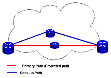
To protect an MPLS network, you could pre-provision a spare path with exact QoS and traffic-processing characteristics.  This path would be spatially diverse and would be continually exercised and tested for operations. However, it would not be placed online unless there were a failure on the primary protected path.  

This method, known as one-to-one redundancy protection (Figure 7), yields the most protection and reliability, but its cost of implementation can be extreme.


Figure 7: One-to-One Redundancy

A second protection scheme is one-to-many redundancy protection (Figure 8).

In this method, when one path fails, the back-up path takes over. The network shown in the Figure 8 can handle a single path failure, but not two path failures.


Figure 8: One-to-Many Redundancy


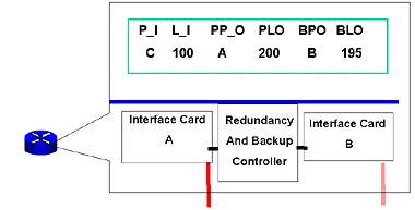
A third protection method is having fault tolerant switches (Figure 9).  In this design, every switch features inbuilt redundant functions – from power supplies to network cards. The drawing shows redundant network cards with a back-up controller.  Take note that the one item in common, and not redundant, is the cross-connect tables. If the switching data becomes corrupt, the fault tolerant hardware cannot address this problem.


Figure 9: Fault Tolerant Equipment

Now that you know the three network protection designs (one-to-one, one-to-many, and fault-tolerant hardware) and two methods for detecting a network failure (heartbeat and error message), we need to talk about which layers and protocols are responsible for fault detection and recovery.

Remembering that the further the data progresses up the OSI stack, the longer the recovery will take, it makes sense to attempt to detect failures at the physical level first.

MPLS could rely on the layer-1 or layer-2 protocols to perform error detection and correction.  MPLS could run on a protected SONET ring, or it could use ATM and Frame Relay fault-management programs for link and path protection. In addition to the protection MPLS networks could experience via SONET, ATM or Frame Relay, IP has its recovery mechanism in routing protocols, such as OSPF or IGP.

With all these levels of protection already in place, why does MPLS need additional protection? Because there is no protocol that is responsible for ensuring the quality of the link, tunnel, or call placed on an MPLS link. The MPLS failure-recovery protocol must not only perform rapid switching, but it must also ensure that the selected path is pre-qualified to take the traffic loads while maintaining QoS conditions. If traffic loads become a problem, MPLS must be able to offload lower-priority traffic to other links.

Knowing that MPLS must be responsible for sending traffic from a failed link to a link of equal quality, let’s look at the two error-detection methods as they apply to MPLS.

MPLS Error Detection

The LDP and CR-LDP protocols contain an error message type-length value (TLV) in their protocols to report link and node errors.  However, there are two main disadvantages to this method: (1) it takes time to send the error message, and (2) since LDP is a connection-oriented message, the notification message may never arrive if the link is down.

An alternative approach to error detection is to use the heartbeat method that is found at the heart of the RSVP-TE protocol. RSVP has features that make it a good alternative for an error- message model. RSVP is a soft-state protocol that requires refreshing – i.e., if the link is not refreshed, then the link is torn down. No error messages are required, and rapid recovery (rapid reroute) is possible if there is a pre-provisioned path.  If RSVP-TE is already used as a signaling protocol, the additional overhead needed for rapid recovery is insignificant.

Rapid reroute is a process in which a link failure can be detected without the need for signaling. Because RSVP-TE offers soft-state signaling, it can handle a rapid reroute.

Many vendors are using the RSVP-TE for rapid recovery of tunnels and calls, but in doing so, other MPLS options are restricted. For example, labels are allocated per switch, not per interface. Another restriction is that RSVP-TE must be used for a signaling protocol.

RSVP-TE Protection

In RSVP-TE protection, there are two methods used to protect the network: link protection and node protection. 

In link protection, a single link is protected with a pre-provisioned backup link. If there is a failure in the link, the switches will open the pre-provisioned path (Figure 10).


Figure 10: RSVP-TE with Link Protection

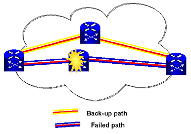
In a node failure, an entire node or switch could fail, and thus, all links attached to the node will fail.  With node protection, a pre-provisioned tunnel is provided around the failed node (Figure 11).


Figure 11: RSVP-TE with Node Protection

Thrashing Links

A discussion about fault-tolerant networks would not be complete without mentioning thrashing links. Thrashing is a phenomenon that occurs when paths are quickly switched back and forth.  For example: In a network with two paths (primary and back-up), the primary path fails and the back-up path is placed in service. The primary path self-heals and is switched back into service, only to fail again.

Thrashing is primarily caused by intermittent failures of primary paths and pre-programmed switchback timers. In order to overcome thrashing, the protocols and the switches must use hold-down times. For example, some programs allow one minute for the first hold-down time and set a trigger so that on the second switchback, operator intervention is required to perform a switchover and to prevent thrashing.

Summary

Building a fault-tolerant, rapid recovery network is new to the data world. One reason is that data communications philosophy is that the data will get there or it will be retransmitted. This philosophy does not work well in voice networks. To make MPLS competitive with ATM and on par with voice networks, rapid recovery must be implemented.

There are several methods under study to provide network protection. Vendors recommend approaches that are supported by their overall design concepts and specifications; therefore, failure recovery is not necessarily interoperable among different vendors. Design teams must carefully select vendors with interoperable recovery methods.

The failure recovery method that has received much favorable press lately is RSVP-TE. The soft-state operations of RSVP-TE make it very suitable for failure recovery.  One reason is that the polling (reservation/path) functions are already in place for signaling.  If RSVP-TE is already used for a signaling protocol, it makes a logical selection to protect your MPLS tunnels.

MPLS Resource Sites:

A Framework for MPLS Based Recoveryhttp://www.ietf.org/internet-drafts/draft-ietf-mpls-recovery-frmwrk-03.txt
Surviving Failures in MPLS Networkshttp://www.dataconnection.com/download/mplsprotwp.pdf 
MPLS Links Pagehttp://www.rickgallaher.com/   (click on the MPLS Links tab)
Network Traininghttp://www.globalknowledge.com

Special Thanks

I would like to thank Ben Gallaher, Susan Gallaher, and Amy Quinn for their assistance, reviewing, and editing.

A special thank you to all those who assisted me with information and research on the MPLSRC-OP /mail list, especially: Robert Raszuk.


Rick Gallaher, CISSP, is owner of Dragonfly Associates LLC http://dragonfly-associates.com and author of  Rick Gallaher's MPLS Training Guide